Ltspice Two Stage Op Amp
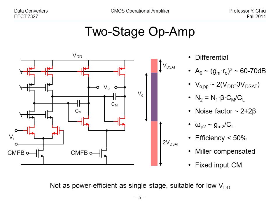
- Aug 24, 2016 As two stage operational amplifiers (op amps) are mostly used to achieve high dc gain and large output voltage swing, which is achieved by frequency compensation 1, 3, 4. In general, a frequency compensation is essential for closed-loop stability as op amp.
- To simulate an op amp in LTSpice, begin by opening the component library, searching for “UniversalOpamp2” and clicking ok. Simulating an op amp. Connect the positive, negative, and output terminals of the op amp to the rest of the circuit. An additional step before simulating most integrated circuits (ICs) such as an op amp is to power the device.
Running open-loop, the op amp output is saturated at 0V. You can add negative DC feedback to bias the op amp in its active region. That is provided below by the addition of R1 and C2, which act as low-pass filter feedback giving a DC gain of 1. Their RC time-constant value is very large so the AC response is not affected.
I am trying to design a two stage opamp. I have gone through texts to equip with basic ideas to design a opamp. The problem is dont know how to choose the ICMR Values and the values of Vth1max, Vth1 min, Vth3max. The Design Procedure i used is as follows.
(μnCox≈246.74 and μpcox≈92.75 * I have calculated using the model file please suggest if I am correct)

Specifications
Gain>=60dB
Power Supply : ±1.8V
GBW=5MHZ
PM>=60°
SR>=10V/μs
CLoad=10Pf
ICMR= ± 1.6V
________________________________________________________________
at Vin = - 1.6 , Vth1min = 0.31 Vth3min = 0.432
at Vin = + 1.6 , Vth1max = 0.622 Vth3max = 0.433
These values are found using the simulation of the
diff amp in the Circuit shown in the opamp.asy file
I hope the values are correct.
_______________________________________________________________
Two Stage Op Amp Design
Design
1. Cc=0.22*CLoad=2.2pF ≈3pf(adjusted)
2. I5=SR*Cc= 10*3= 30μ
3. gm1=GBW*Cc*2π=94.24μ
5. VDSSAT5 = ICMRmin-VSS-√(I5/β1)-Vth1max
Ltspice Op Amp
(W/L)5 = (2*I5/(μnCox*VDSsat5^2)) = 22.91 ≈ 23
(W/L)6 = (gm6*(W/L)4)/gm4 = 131.28 ≈131
Using These Values I have simulated the circuit. With these values I assume that the Gain should be >60dB. but I am getting just above -10dB. What am I Doing Wrong. I am stuck, Please suggest me what should I do? I also need to simulate the settling time, psrr, open loop gain and closed loop gain and other parameters of opamp using LTSPICE. please suggest how can I do that too.
Also, When I simulate using ground instead of VSS, I get gain >60dB. ??
I am sorry , the mosfets are named badly in the picture but in the schematics file, its named correctly.
Hope I will be helped
Introduction
LTspice is a free SPICE simulation software tool with schematic capture, waveform viewer, and many enhancements that runs on both Windows and Mac OS X. I use it to research circuit behavior and quickly experiment with new circuits for my lab before prototyping a PCB (Printed Circuit Board) design. The learning curve is easy to conquer thanks to support by Analog Devices, Yahoo's LTspice Support Group and its compatibility with most common SPICE models supplied by chip vendors.
This Instructable will demonstrate how to go beyond the component library supplied with LTspice by incorporating an LMV321 op-amp model from three different chip vendors to create a simple amplifier schematic as shown in the drawing. Each of these models highlight different methods available within LTspice for use with the wide variety of component models supplied from various vendor websites. Each of these models present different performance features as well. To highlight these performance issues I reuse these three models in a Current-to-Voltage design as well.
The target audience are those with some experience placing components on a schematic and running a simulation. By the end of this tutorial you will know how to interpret the .SUBCKT command within manufacturer models for use with LTspice's opamp2 Pin Table and Attribute editors to use manufacturer parts within your simulations.